


Products Description
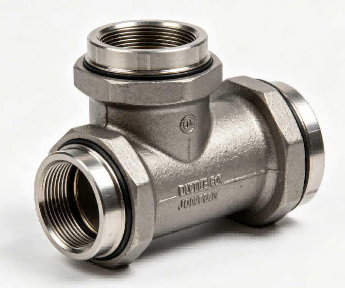
EX joint socket couplings and bends provide restrained push-on connections for ductile iron pipelines. No thrust blocks needed. Ideal for bends, straight pipe joints, and directional drilling applications.

Key Technical Specifications
| Item | Specification |
|---|---|
| Product Type | EX Joint Socket Couplings / EX Joint Bends |
| Joint Type | Restrained Push-On (EX Joint) |
| Nominal Size | DN80 – DN2000 |
| Pressure Rating | PN10 / PN16 / PN25 / PN40 |
| Material | Ductile Iron EN-GJS-400-15 (ASTM A536 65-45-12) |
| Coupling Function | Connect two plain pipe ends with thrust restraint |
| Bend Function | Change direction with thrust restraint at the bend |
| Bend Angles | 11.25°, 22.5°, 45°, 90° (custom angles available) |
| Gasket Material | EPDM (water) / NBR (oil) / FKM (chemicals) |
| Deflection per Joint | Up to 5 degrees (depending on size) |
| Inner Lining | Cement Mortar / HAC / Epoxy / Polyurethane |
| Outer Coating | Blue Epoxy (RAL 5005) / Bitumen / Zinc + Epoxy |
| Standards | EN 545 (Water) / EN 598 (Sewage) / ISO 2531 |
Product Features
EX Joint Socket Coupling – Restrain Pipe Joints Without Welding or Bolts
Two plain pipe ends meet at the coupling. Push each pipe into the socket from opposite ends. Lock both sides with EX joint segments. The coupling restrains both pipes. No axial movement. No pull-apart.
EX Joint Bend – Eliminate Concrete Thrust Blocks Forever
A bend under pressure wants to push apart. Standard bends need heavy concrete thrust blocks. EX joint bends lock the pipes inside the sockets. The bend itself resists the thrust force. No concrete. No excavation. No curing time.
Push-On Assembly Means Faster Installation
Your crew already knows push-on joints. Lubricate the gasket. Push the pipe into the socket. Insert locking segments. Tighten set screws. Same steps for couplings and bends. No special training. No new tools.
Application & Scope
Straight Pipe Joints in Thrust Restraint Areas – Pipe joints near bends, tees, or valves experience thrust forces. EX couplings restrain these joints. No concrete needed at every joint.
Directional Drilling (HDD) Pulled Sections – The entire pulled length needs restrained joints. EX couplings provide full restraint. They also allow deflection for the drilled curve.
Seismic Zones – Standard push-on joints can pull apart during ground movement. EX couplings lock the pipes together. The joint deflects but does not separate.
River Crossings and Aerial Spans – Pipes on bridges or above ground need restraint against thermal expansion and contraction. EX couplings lock the pipe length while allowing some movement.
Pipeline Abandonment and Pull-Through – When pulling a new pipe through an old casing, restrained joints prevent separation during the pull.
Materials & Standards Compliance
| Component | Standard Material | Specification | Upgrade Option |
|---|---|---|---|
| Coupling body | Ductile Iron EN-GJS-400-15 | 400 MPa tensile, 15% elongation | EN-GJS-500-7 |
| Rubber gasket | EPDM | Shore A 70-75, drinking water approved | NBR, FKM (Viton) |
| Locking segments | Ductile iron or hardened steel | Segmented ring, heat treated | Stainless steel |
| Set screws | Carbon steel Grade 8.8 | Zinc plated, hex head | Stainless steel A2 or A4 |
| End caps (shipping) | Plastic | Protects gasket during transport | N/A |
Accessories
EPDM Gaskets (Pre-Installed or Spare) – Each coupling includes two gaskets. Each bend includes two gaskets. Spare gaskets available.
Locking Segment Sets – Each EX joint includes one set of segments per socket. Couplings need two sets. Bends need two sets. Spare sets for field backup.
Set Screws with Torque Specification – Each socket uses 2 to 8 set screws. Torque value printed on fitting label. Spare screws included.
Gasket Lubricant (Water-Based, Non-Toxic) – Safe for drinking water. One tub per 50 sockets.
Installation Tool Kit – Includes lubricant brush, depth marking gauge, hex key for set screws, torque wrench adapter, and disassembly tool.
Pipe End Chamfering Tool – Removes sharp edges from cut pipe ends. Prevents gasket damage during assembly.
Depth Marking Gauge – Tool to mark correct insertion depth on pipe. Ensures full engagement without over-insertion.
Disassembly Tool – Releases locking segments for joint disassembly. Allows pipe removal for maintenance or modification.
EX Joint to Flange Adaptor – EX socket on one end, flange on the other. Connect restrained pipeline to flanged equipment.
Performance Testing
Hydrostatic Pressure Test (Shell) – Fill fitting with water. Pressurize to 1.5x rated pressure. Hold for 60 seconds. No water through casting wall. No porosity. No weeping.
Gasket Seal Test (Assembly Test) – Assemble EX joint to plain pipe sample. Pressurize to 1.25x rated pressure. Hold for 5 minutes. No water leakage past gasket.
Pull-Out Resistance Test – Assemble EX joint to pipe sample. Apply axial tension force. Requirement: Force must exceed 2x pressure thrust for the pipe size. Joint must not pull apart.
Deflection Test (Couplings and Bends) – Assemble joint to pipe sample. Deflect to specified maximum (3° to 5°). Pressurize to rated pressure. No joint separation. No gasket leakage.
Set Screw Retention Test – Tighten set screws to specified torque. Apply vibration (transport simulation). Screws must not back out.
Lining Thickness and Adhesion Test – Measure lining thickness at multiple points. Perform impact or cross-cut adhesion test.
Application Deep Dive
The Problem with Standard Push-On Joints at Bends:
A standard push-on joint (T-type or K-type) seals with a rubber gasket. The gasket holds pressure. But it does not resist tension. If you pull the pipe, it slides out.
At a bend, internal pressure creates a net thrust force. That force tries to pull the pipe out of the bend socket. Without restraint, the joint separates.
The Standard Solution – Concrete Thrust Blocks:
Place a large concrete block behind the bend. The block presses against undisturbed soil. The block resists the thrust force.


