



Products Description
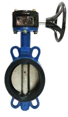
Heavy‑duty wafer butterfly valve with worm gear operator. Ideal for large pipe sizes where hand levers become too hard to turn. Self‑locking gear holds position without a brake.

Key Technical Specifications
| Item | Specification |
|---|---|
| Valve Type | Wafer Butterfly Valve, Worm Gear Operated |
| Operation | Manual Worm Gear (self‑locking) |
| Nominal Size | DN200 – DN1200 |
| Pressure Rating | PN10 / PN16 / ANSI150 |
| Connection Type | Wafer (between flanges) |
| Body Material | ASTM A536 / EN GJS‑450 Ductile Iron |
| Disc Material | SS304 / SS316 / Coated Ductile Iron |
| Seat Material | EPDM / NBR / FKM / PTFE |
| Stem Material | SS304 / SS316 |
| Gear Ratio | 20:1 to 60:1 depending on size |
| Handwheel Diameter | 200mm to 400mm |
| Position Indicator | Yes (large dial, 0° to 90°) |
| Self‑Locking | Yes (worm gear design) |
| Top Flange | ISO 5211 (for actuator conversion) |
| Coating | Fusion Bonded Epoxy (250‑300 microns) |
| Standards | ISO 5752 / EN 593 / API 609 |
Product Features
Worm Gear Makes Large Valves Easy to Turn
A DN500 butterfly valve needs over 80 kg of force at a lever handle. No one can turn that easily. Our worm gear reduces the force by 40 to 1. You turn a small handwheel with very little effort. One finger can operate a DN600 valve.
Self‑Locking Gear Holds Position Without a Brake
The worm gear design locks itself. When you stop turning the handwheel, the valve stays exactly where you left it. No brake needed. No handle strap. The valve will not move even with high flow or pressure.
Smooth, Precise Disc Positioning
The gear ratio gives you fine control over disc position. One full turn of the handwheel moves the disc only 9 degrees (for a 40:1 gear). You can adjust flow very precisely. Set the valve at 10%, 30%, or 75% open.
Clear Position Indicator Shows Disc Angle
The gear operator has a large, easy‑to‑read position indicator. You see at a glance if the valve is open, closed, or partially open. The indicator shows 0° (closed), 90° (open), and every position in between.
Application & Scope
Water Transmission Mains (DN350 and larger) – Large pipelines need reliable isolation valves. Worm gear makes operation easy. Self‑locking keeps the valve in position.
Pump Station Discharge Lines – High pressure and flow at pump outlets. Worm gear holds position against dynamic forces. Operators open and close valves without strain.
Raw Water Intake Lines – Valves at river or lake intakes are often large and hard to reach. Worm gear allows one person to operate from a safe distance.
Wastewater Treatment Plant Aeration Basins – Frequent operation for maintenance cycles. Worm gear handles thousands of cycles without wear. Self‑locking prevents accidental closure.
HVAC Chilled Water Plants – Large buildings have chilled water pipes up to DN800. Worm gear valves give maintenance staff precise control for flow balancing.
Industrial Cooling Towers – Large cooling towers need big isolation valves. Worm gear makes quarterly maintenance easy. Position indicator shows valve status from a distance.
Power Plant Cooling Water – Condenser cooling water lines are often DN1000 or larger. Worm gear operators provide smooth operation. Self‑locking is critical for safety.
Materials & Standards Compliance
| Component | Standard Material | Properties | Upgrade Option |
|---|---|---|---|
| Body | Ductile Iron ASTM A536 65‑45‑12 | 450 MPa tensile, 12% elongation | SS316 for corrosive environments |
| Disc | SS304 | Good corrosion resistance for water | SS316 (salt water), Nylon‑coated DI (abrasion) |
| Seat | EPDM | -20°C to 80°C, excellent for water | NBR, FKM (Viton), PTFE |
| Stem | SS304 | Good strength, corrosion resistant | SS316 for salt water or chemicals |
| Gear housing | Cast iron (painted) | Strong, impact resistant | Aluminum alloy (lighter) |
| Gears | Hardened steel | Wear resistant, long life | Stainless steel for food/pharma |
| Bearings | Sealed ball bearings | Low friction, no maintenance | Bronze sleeve bearings |
| Handwheel | Ductile iron with plastic grip | Durable, comfortable grip | Stainless steel |
| Coating | Fusion Bonded Epoxy | 250-300 microns, RAL 5005 blue | Custom color, polyurethane |
Accessories & Optional Configurations
Padlockable Handwheel – Add a padlock hasp to the handwheel hub. Lock the valve in open, closed, or any position. Essential for fire protection and security applications.
Extended Handwheel Shaft – For valves installed in pits or deep vaults. Shaft extends from the valve up to ground level. Operate the valve without entering the pit. Available in 1m, 2m, or custom lengths.
Chainwheel Operator – For overhead valves or valves in high ceilings. A chain hangs down from the handwheel. Pull the chain to operate the valve. No ladder needed.
Electric Actuator Conversion Kit – Replace the handwheel with an electric actuator. The gear stays in place. Convert from manual to automated without removing the valve from the pipeline.
Pneumatic Actuator Conversion Kit – For hazardous areas where electricity is not allowed. Bolt on a pneumatic actuator. Use plant compressed air to operate.
Position Indicator with Electrical Feedback – Add limit switches to the gear operator. The control room knows if the valve is open or closed. Works with SCADA and building automation systems.
Performance Testing
Air‑Tightness Test (ISO 5208 Rate A – Zero Leakage):
Close the valve fully.
Apply 0.6 bar air pressure to one side.
Submerge the valve in water.
Watch for bubbles for 60 seconds.
Result: No bubbles means zero leakage. This is the strictest test for soft‑seated valves.
Hydrostatic Seat Test (High Pressure):
Close the valve fully.
Apply 1.1 times rated pressure with water (PN16 → 17.6 bar).
Hold pressure for 60 seconds.
Measure any water passing through the seat.
Result: Zero leakage allowed. Record result on test certificate.
Hydrostatic Shell Test (Body Strength):
Open the valve partially (to protect the seat from over‑compression).
Fill the body with water.
Apply 1.5 times rated pressure (PN16 → 24 bar).
Hold for 60 seconds.
Result: No water through the body casting, disc, or stem seals.
Quality Assurance
Gear Operator Function Test:
Turn the handwheel from fully closed to fully open.
Count the turns to verify gear ratio.
Check that the handwheel turns smoothly. No grinding or binding.
Self‑Locking Test:
Stop the handwheel at several positions.
Apply force to the disc through water pressure.
Result: The handwheel must not back‑drive. The valve stays in position.
Position Indicator Accuracy Test:
Set the disc at 0° (closed), 45° (half open), and 90° (open).
Verify the position indicator shows the correct angles.
Result: Accuracy must be within +/- 2 degrees.
Coating Thickness Test:
Measure epoxy coating at six points on the valve body.
Minimum thickness: 250 microns. Maximum: 350 microns.
No thin spots. No bare metal. No bubbles.
Material Verification:
Check mill certificates for body, disc, stem, seat, and gear materials.
Trace each heat number to raw material source.
Special Testing for Large Valves (DN500 and above):
Dimensional Check – Measure face‑to‑face length, flange bolt hole alignment, and overall height. Large castings can warp. Reject any valve that does not meet drawing dimensions.
Seat Compression Test – Measure the rubber seat compression after assembly. Proper compression is critical for large valves. Too little compression causes leakage. Too much compression makes operation difficult.
Operating Torque Test – Measure the torque required to operate the valve. Compare to the gear operator's rated input torque. Valve must operate with at least 30% safety margin.
Installation Guide
Tools Needed:
Flange bolts (appropriate length for wafer valve)
Torque wrench
Cross pattern tightening sequence
Lifting equipment for DN500 and above
Step‑by‑Step Installation:
Inspect the valve – Check for shipping damage. Verify the disc moves freely. Use the handwheel to close the valve.
Center the valve between flanges – The valve must be centered. The disc must not touch the pipe when rotating. Use alignment pins or a centering tool.
Insert flange bolts – Bolts pass through one flange, through the valve body holes, and through the other flange. Use washers under nuts.
Tighten bolts in cross pattern – Start with the bolt at 12 o'clock. Tighten lightly. Move to 6 o'clock. Then 3 o'clock. Then 9 o'clock. Continue pattern.
Tighten to final torque – Use torque wrench. Follow torque values below. Do not over‑tighten. Over‑tightening compresses the seat and makes operation difficult.
Operate valve – Turn the handwheel to open and close. Verify smooth operation. If stiff, flanges may be over‑tightened.


